algorithmic modeling for Rhino
I undertook this project to learn more about the use of parametric systems in urban design. My intentions were to recreate the Kartal Pendik Masterplan and understand the principles behind it. As this is an ongoing project I do not expect to create exact copy of the project, but to get myself thinking in a linear logical way despite the experimental nature of the project. Here is some more information on the project by the lead architect Patrick Schumacher: The project is to constitute a sub-centre on Istanbul’s Asian side to release the pressure on the historic centre. The site is being reclaimed from industrial estates and is flanked with the small grain fabric of sub-urban towns. The parametricist taboo of unmediated juxtapositions implied that we took the adjacent context - in particular the incoming lines of circulation - as an important input for the generation of the urban geometry. Maya’s hair dynamic tool achieved a parametrically tuned bundling of the incoming paths into larger roads enclosing larger sites. The resultant lateral path system that exhibits the basic properties of Frei Otto’s minimizing detour network. The longitudinal direction was imposed via a primary artery with a series of subsidiary roads running in parallel.(Schumacher,2008) For more information please watch the video .
For project files package go to www.wirehouse.co.uk/projects/kartal-pendik-masterplan-breakdown/
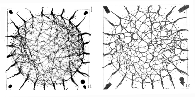
Wool-thread definition
Wool-thread simulation

Marek Kolodziejczyk, Wool-thread model to compute optimised detour path networks, Institute for Lightweight Structures (ILEK), Stuttgart, 1991
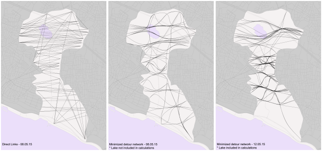
Depending on the adjustable parameter of the thread’s sur-length, the apparatus – through the fusion of threads – computes a solution that significantly reduces the overall length of the path system while maintaining a low average detour factor. (Schumacher,2008) However the following experiment is developed using Rhino and Grasshopper instead of Maya, so the results are similar. The definition logic is to connect the intersection points between the area of interest and the major road and thus to create a network. It is then refined by deleting the connections which do not meet the criteria: fall outside the domain of [400,2000] metres length and form angles outside the domain of [0,60] degrees with the area boundary at their end points. The successful lines are then used in wool-thread model simulation.
Kartal Pendik Analysis Definition
Wool-thread simulation output
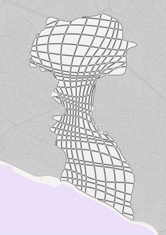
24.09.15 After a few months break from the project I had some thoughts how to push it further. Next steps I made were towards the next stage of the project - developing deformed grid. Guessing exact parameters is almost impossible, so instead many sliders were included in the definition for manual control. These were used to achieve the most similar variation of the grid to the original design. It may have been said somewhere above in a true parametric design the manual work should be kept to minimum, because often behind such manually controlled sliders are parameters based on intensive research. However lets continue. The deformed grid was developed by using the boundary curve of the area of interest ,which was broken into 4 parts- North, East, West and South. I this particular scenario the East/West pair seem to play crucial role, because their are longer than the North/South pair which means having more site information. The main idea for the deformed grid is adaptation or integration (which ever is more appropriate) to the surrounding context. Apart from East/West curves another constant is the design is the central spine curve. Using the best to fit method several curves longitude curves where created by 'tweening' the E/W curves and the central spine curve at specific parameters. These longitude curves serve as the base of the deformed grid. They are split into segments and the control points are use to move to or away from preselected attractor and repeller points to create the later deformed grid design. The final longitude and latitude curves are used to split the area into regions/blocks which were off setted inwards to create the roads. For more detailed breakdown follow the Grasshopper definition above.
Grid Deformation Animation
Deformed Grid
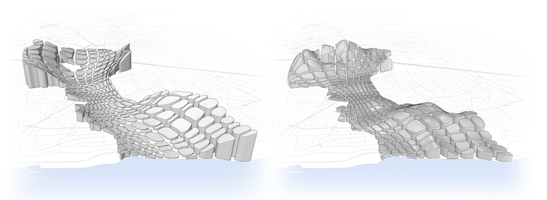
21.05.16 To finalise the project the region are extruded. The extrusion options are endless. Below are shown extrusion by distance of regions to middle curve, which creates a valley effect and extrusion by size of region, following 'the larger the taller' logic.
 Volumes by distance to mid curve (Left) Volumes by area m2 (Right)
Views: 8015
Comment
-
Comment by sarwar on September 28, 2022 at 2:55pm
-
Comment by maiabdelsalam on January 25, 2022 at 1:16pm
-
Thank you for the tutorial.
-
Comment by Tsvetan Hristov on January 23, 2021 at 4:41am
-
There is a download link on the page below.
https://www.wirehouse.co.uk/projects/kartal-pendik-masterplan-break...
-
Comment by Kat Mon on January 22, 2021 at 2:56pm
-
Hi, this project is great, Where can I get the files? on the website the file has expired, can you upload it again? Please...
-
Comment by İsmail Hayat on February 1, 2020 at 2:43pm
-
Really A great study. Thanks for this solve.
-
Comment by Bethany Bauch on October 16, 2019 at 6:37am
-
Wow, this is absolutely great article about Kartal Pendik Masterplan particularly for those who were unaware about this Masterplan. I think, the most important thing you given here is exact detail of this Masterplan. You can visit essayontime.com.au website to complete essays in Australia without any trouble. I am extremely pleased for your article which contains a unique taste of information of its readers.
-
Comment by arav kumar on May 12, 2019 at 4:19am
-
Hi ...Really nice project!!. Could you re-link the file again. Its not there anymore in the dropbox link.
Thanks
-
Comment by peng yang on December 21, 2018 at 12:58am
-
Inspairing PROJECT!!!
-
Comment by Alyssa Parsons on April 17, 2018 at 8:35pm
-
This is very interesting!
-
Comment by Juan Felipe Betancur Martinez on September 11, 2017 at 7:31am
-
Thank You so much!!!
© 2025 Created by Scott Davidson.
Powered by
![]()


You need to be a member of Grasshopper to add comments!